Rohini Contractor and Adrian Janus, student teaching assistants, and Yusef Patel, lecturer, Bachelor of Architectural Studies, Unitec Institute of Technology, Auckland
This article describes an assignment that enabled students to undertake a design-and-build project. The educational facility, Tech Futures Lab, acted as client for which an interior was designed and fabricated using rapid learning process. In architectural design, 3D modelling software is becoming more readily available in fabrication activities. If the software used dictates the design, it can lead to the oversimplification of a rational, well thought-out design process. This article describes how students created ‘iterative prototypes’, and how this experience facilitated abilities to translate virtual designs into real-world constructs. Using a hybrid of digital and conventional making methods, the paper describes a modern studio, where students can actively participate in how making and design are taught.
Architectural pedagogy; digital fabrication; prototyping; iterative design; Architecture
Advancements in technology within architectural practice have substantially changed the way making is being taught in tertiary institutions (Burgess and Mamou-Mani, 2015). This process is forcing architects, engineers and builders to throw away the rule book, and rethink how they approach workflow, presentation of data and sharing of ideas (Chaszar and Glymph, 2010). Within the Architecture classroom, courses need to adopt and adapt to prepare students for a professional industry that is rapidly and constantly subject to digital revolutions.
This article provides a student perspective, discussing the importance of design-and-build assignments by exploring our experiences on the ‘Tech Futures Lab’ project, which involved learning to communicate and use digital production technologies in a group setting. All the students that were involved in the project were completing their third year of studies in the degree of Bachelor of Architectural Studies at Unitec Institute of Technology (Unitec), Auckland, New Zealand. The studio project promised the participants to experience the process of both designing and building a project for a real-life client within a safe environment.
The project ran in semester one of 2016, and was commissioned by national award-winning educator and founder of the newly established tertiary provider ‘Tech Futures Lab’, Frances Valentine. Tech Futures Lab was founded in collaboration with Unitec to provide mature students a pathway to learn, upskill or innovate within an ever-changing technological world. Our brief was to retrofit an old delivery bay and convert it into a reception space in time for the institutions’ first classes in semester two at its inaugural premises in the upmarket Auckland suburb of New Market.
To keep in line with the themes of the courses Tech Futures provides and a limited time frame, Valentine asked us to use digital fabrication technologies and readily available materials – specifically plywood – as the main design driver. The design of the space had to include three major design features. The first was to create a new balustrade and handrail system. The second was some form of acoustic panels to dampen noise. The third was the need for privacy and security screens at the front the space where the semi-transparent roller door is located. The fourth element was to incorporate setting elements to ensure visitors or students to Tech Futures had a place to rest while waiting for meetings or classes.
The assessment of the course was specifically designed to ensure that we took on as much of the responsibility as possible. This meant, we not only had to design, fabricate and install the commission work, but also manage the $20,000 budget and communicate with suppliers, the client and tradespeople. The budget was fully funded by Tech Futures Lab. Labour cost and workshop resources were all funded by Unitec. For a successful outcome to be produced, participants were required to collaborate and learn together. The fabrication process emphasized that conventional skills and practical thinking are required even when utilising digital tools.
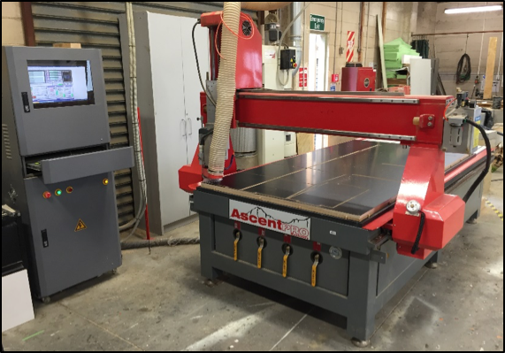
We initially selected this fabrication course predominantly to learn 3D modelling software and how to operate a Computer Numerical Control (CNC) Router (Figure 1) that can cut and carve artefacts out of material such as plywood or large blocks of timber. We quickly learned that digital production technologies can be a powerful product design tool, but that they can also easily mislead us into producing superficial outcomes. A scaled model, for example, can easily replicate a design created using software via a laser cutter or 3D printer, but the result can often fail to accurately reflect material considerations, functional use and the aesthetic quality of a full-sized practical product.
Architectural software has the capacity to produce designs that may look appealing, interesting or exciting, but often fail to meet practical needs of people or efficient methods of fabrication. Software such as Autodesk’s ‘Fusion 360’, can oversimplify the design-to-making process, potentially diminishing the creativity within craft. This is exemplified by how accessible digital tools are. It is easy to create basic mock ups, indicating that ubiquity of software can dictate design quality, ultimately undermining a potentially bespoke design (Parsons, 2014). However, Willis and Woodward advise that, when approached with the correct workflow, this process can lead to effective and meaningful results (2010). As a group, the fifteen students understood that a tailored workflow process needed to be developed to ensure each tool, whether digital or not, was utilised effectively to transform this space.
A majority of the students who took part in this project assignment had limited or no experience with software or digital tools. As the project required us to use software, it aimed to integrate conventional workshop tools within a digital workflow. The pedagogical approach described within this paper shows that digital production can be more than simply a tool for design and production of a product for subsequent printing of cut components on the CNC machine for subsequent assembly. There is a need for a designer or fabricator to understand and work through problems such as materiality, assembly process and technique, if frustration during the assembly stages and a compromised product are to be avoided.
We started the course two-thirds the way through semester one and were required to complete the project in time for the opening classes at Tech Futures lab in semester two. In total we were given about five weeks to design, prototype, prefabricate and fit out the space. The lecturer programmed an extra week’s contingency time into the course just in case not all activities were complete. Ultimately, it proved useful as it helped us refine or replace elements that had not been fabricated correctly.
The project essentially was set up as a ‘crash course’ in design, making and collaboration. We were tasked with learning the software, designing and prototyping in a short time, to investigate the design process beyond the digital. Within our workflow, we scheduled time restrictive deadlines for each stage, so we could test and discuss the design. Regular scheduled presentations at two day intervals allowed for each member to present developments and be critiqued by the whole group, ensuring a high standard of quality was maintained.
As this course and assignment aimed to teach us that digital fabrication requires more than software knowledge, an understanding of conventional making skills was vital. The creation of the interior we were commissioned to produce required us to adopt a flexible but rigorous approach not only to design, but also to building.
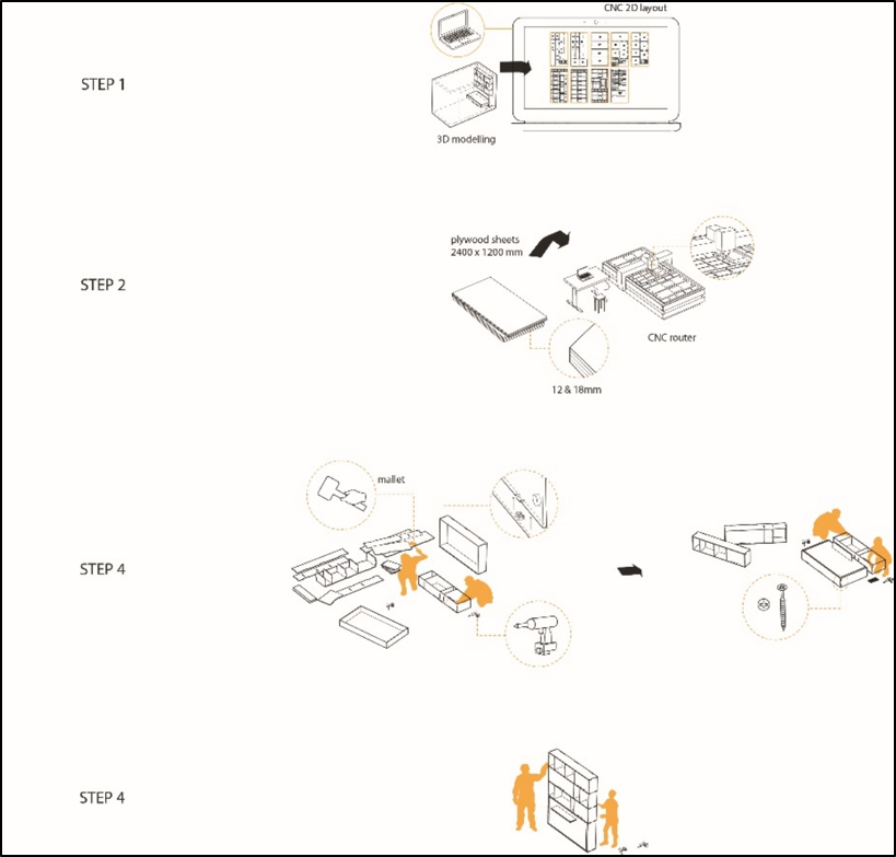
A large majority of work for the project was working on the ‘file to factory’ process, which enables the designer-maker to design and simulate components via software. They can subsequently print or cut components on the CNC machine for assembly (Figure 2).
Digital fabrication has augmented major manufacturing techniques, with the more conventional subtractive cutting method, and the more recent additive layer methods commonly known as 3D printing. Subtractive cutting techniques can be identified either in two dimensional or three-dimensional contexts. It works on the basis of removing material in order to create a designed form. More recently the sharp reduction in cost associated with automation and mechanisation is increasing accessibility, allowing everyday designers to work with advanced computer numerically controlled (CNC) machines. Data within a virtual model can be interpreted by computer software to control machines within the fabrication process. The data can be extracted from surface models or vector line drawings to create instructions for the machine to follow. These instructions are called digital tool paths.
The subtractive CNC milling file to factory process can allow for a more dynamic relationship between computer generated architecture and physical realization. Translating digital information from a digital model into a language that a CNC router can understand can be achieved by commercial software such as RhinoCAM (a plugin to Rhinoceros 3D). The aim of programs like RhinoCAM is for the generation of ‘tool path’ data in a CNC specific programming language called G code. This can be done either by CNC specific software or by tediously writing G Code scripts. Basic variables and parameters such as material size, router bit size and type (i.e. down-cutting, up-cutting or compression) must be set within these programs. However, within most software the user must define the type of path the tool will take, along with other parameters such as speed of cut and revolution per minute (RPM) of the router bit. There are literally thousands of ways to cut or router material. The technician or the designer must decide on the design intent, whether the tool will take a parallel, spiral or sloped path while cutting.
The development of a design through iteration is a staple characteristic of any design process and is a fundamental element of architectural practice. The architectural design process has been likened to the iterative progress within a science experiment in order to resolve problems (Lucas, 2016). The students therefore were asked to employ iterative prototyping, to test, refine and develop individual concepts in order to identify and then resolve faults. This process means that ambitious designs are dismissed, refined and/or validated. In response to the limited timeframe, we adopted an iterative process similar to that of a science experiment (Lucas, 2016). Through prototyping and learning the process, students gain certainty and confidence. These are vital aspects of testing the design, as there is rarely enough time for major amendments to be made before the final production has to be fabricated and installed (Thornton, 2005).
This course and project assignment introduced the students to an unfamiliar environment, where the reality of professional pressures was experienced and made clear during every step of the process. This heavily influenced the final design and group dynamic, requiring the group to move beyond a solo design mentality to cohesive group. Compromises with individual group members’ personal tastes had to take place to ensure a quality outcome was produced. The limitations of the digital tools – specifically with the use of plywood, the budget and CNC router’s limitation of only being able to cut in two dimensions – required us to experiment with a variety of non-digital fabrication methods to achieve a quality outcome.
Our group of students divided the project into three steps, completed over a six-week time frame. The first step was dedicated to learning how to use the software and produce files compatible with laser cutters and CNC routers. The second step was dedicated to iterative prototyping activities and pitching these ideas to the client. The third and final phase commenced prefabricating the CNC components of the design and installing the reception interior in the space.
The first task for each student was to learn the software ‘Rhinoceros 3D’ through designing a piece of furniture. In order to understand the realities of using materials within the fabrication process, we were also required to fabricate our designs using conventional non-digital making processes. Our lecturers and tutors taught us to use joinery tools such as hand planes, belt sanders, the compound mitre saw, bandsaws and the trim router. This exercise taught us that there are consequences when translating designed elements from a virtual to physical realm. These included material optimisation, assembly process and tolerance. It also provided us with the necessary skills to amend, finish or refine components that were beyond the capabilities of the CNC router.
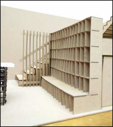
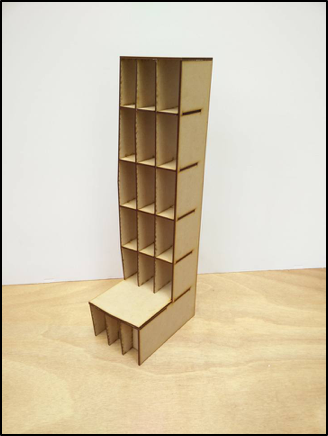
Once we understood both the software and the materials into which these designs translate, we worked collaboratively to develop an efficient design workflow. During this phase, we experimented with digital fabrication tools – specifically the laser cutter and 3d printer - to produce 1:5 scale models (Figures 3a and 3b). In most cases, the process entailed designing various iterations of products on 3D modelling ‘file to factory’ software. The best designs were collectively selected to be fabricated at 1:5 or 1:10 scale. If design refinements were required, we would fix the digital files and remake the scale model. Only when the group was happy with the design, we would move on to test the design with prototypes at either full or half scale.
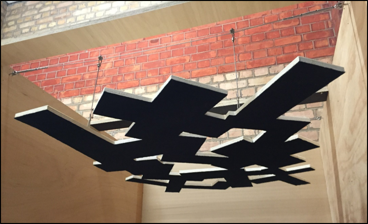
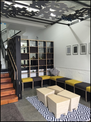
By the end of this phase, we had locked down a conceptual design to refine and develop. We also expanded the brief to include the design of coffee tables to occupy an uninhabited centre focus space. The balustrade and handrail system comprised of several vertical fins with an intersecting handrail and was attached to a bookcase. The main seating elements were designed to be incorporated into the design to provide a dynamic, well-defined space. The acoustic panels - dubbed ‘the cloud’ - were designed to be hung from the ceiling. The design was to be made from a combination of plywood overlaid with felt, to add a softness to the industrial interior.
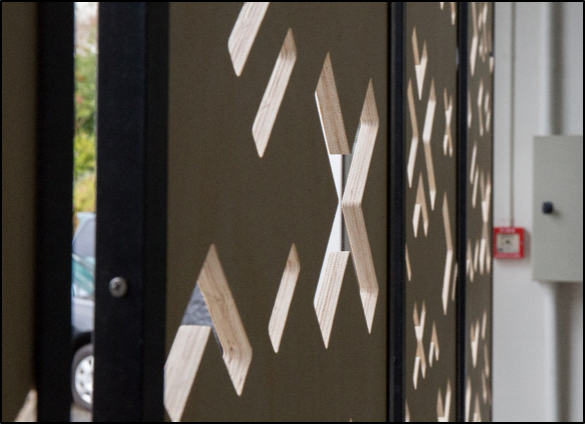
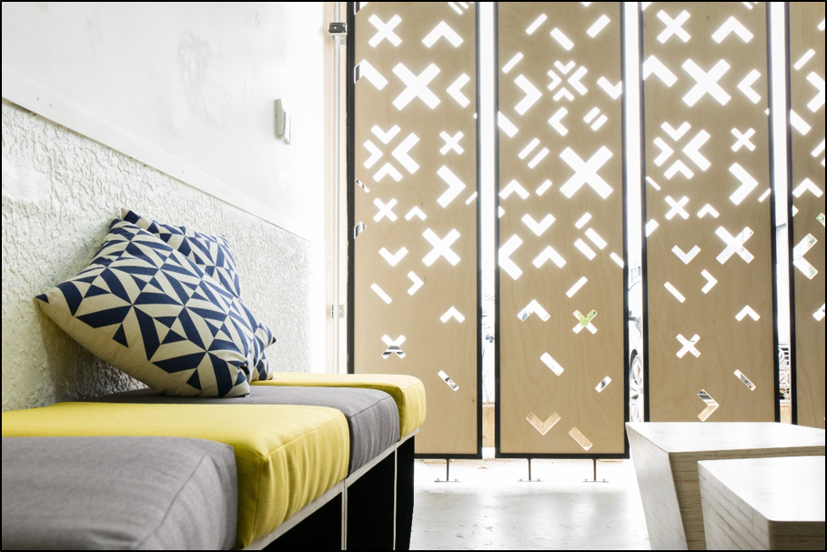
The privacy and security screens at the front of the space were designed to be made out of plywood housed in steel framing. Both the designs for the acoustic panels and the privacy screens incorporated the Tech Futures Lab brand into their designs.
The second project phase required us to engage with the client, suppliers, workshop technicians and other experienced consultants. We learned that the process was not simple. It required several successive presentations and meetings with the client over an intense two-week period, during which time we resolved the design, and issues with delivery and installation of the design, sourced materials, and fabricated and assembled prototype models.
To produce a cohesive design, the group needed to be organised using a productive hierarchy. Establishing an appropriate workspace was also essential for good workflow, as it enhanced the group’s enthusiasm and ability to make, allowing us to bridge digital modelling with the fabrication of small-scale prototypes (Burgess and Mamou-Mani, 2015). At the advice of lecturers, we established groups that each tackled a specific design challenge. From the fifteen students, smaller groups of about four worked to resolve issues surrounding tolerance.
Three layers of hierarchy were formed. One student was elected to be project manager, four students became team leaders and the rest were divided into the respective groups. The project manager organised budgeting, compiled fabrication information, managed communication and tracked progress. The team leaders collated all the work of their groups to make sure the design details and aesthetic language was cohesive with that of other teams.
At first, prototyping activities were viewed as extra work and students were reluctant to take part. As we continued to develop the design, we started to understand that testing in the physical world allowed us to find material and physical inconstancies that had not been represented or apparent in the virtual models. In total, three major problems were revealed during the prototyping stages. The first issue revealed that design developments were not accounting for material tolerance. Calculating a materials tolerance is vital to ensure pieces are cut at the right sizes so they can interlock with ease. The second issue came with amending design details and assembly systems. Amending the assembly systems allowed for greater ease in construction while maintaining the intended look of the design. The third issue came with the materials we used, which at certain points did not meet either the client’s aesthetic preferences or structural requirements.
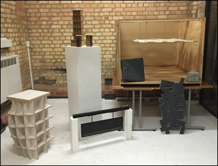
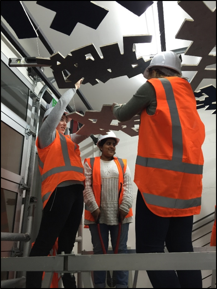
As part of the monitoring of the project, student groups were required to attend design workshops with professionals, who ensured our designs were feasible. This was a useful exercise, as it allowed us to work through problems such as how to hang the ornamental ‘cloud’ acoustic panels (Figure 4). The clouds were a feature the client, Frances Valentine had asked for to give the ceiling texture and help with sound reverberation. We were required to discuss and defend our designs at client meetings. Our first client presentation included a series of scaled laser cut models, mock up prototypes, and diagram banners (Figure 5), which allowed Valentine to critique the design to ensure it fitted with the ‘Tech Futures Lab’ aesthetic. The success of the first meeting convinced Valentine of our abilities and led to successive, less formal, meetings. By the end of this phase, the prototyping activities, the design workshops and the presentations had provided us with the confidence to formulate a budget, a digital fabrication workflow and hand craft making skills needed to execute the interior fit out.
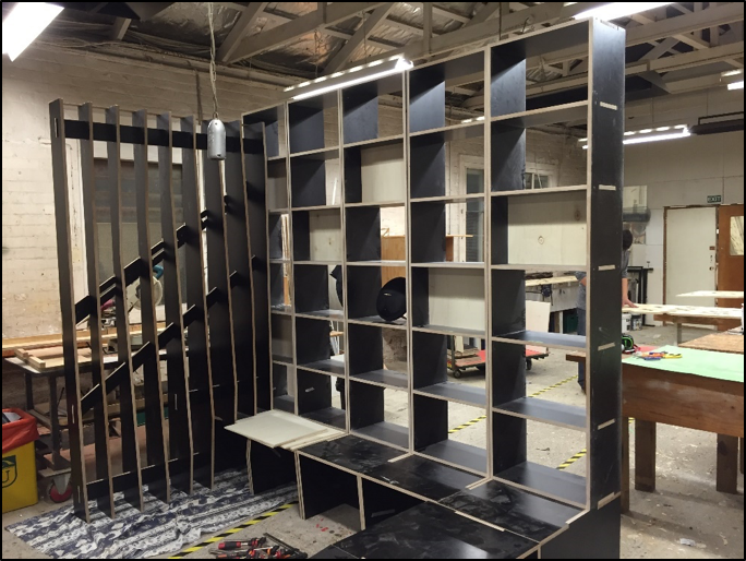
The initial prototyping activities prepared us for the fabrication of components and modules. Using the architecture workshops at UIT, all the components and modules were prefabricated before being transferred and assembled on-site. Despite having done practice tests of this assembly (Figure 6), these tests do not necessarily eliminate problems onsite.
Synchronised communication between the groups was essential in ensuring that the fabrication and assembly process went smoothly. It also became clear that when co-operating with contractors and suppliers, we needed to respect their opening business hours. The 24-hour day that can exist in a studio environment is not applicable on-site, and further to this, other people using the space need to be considered.
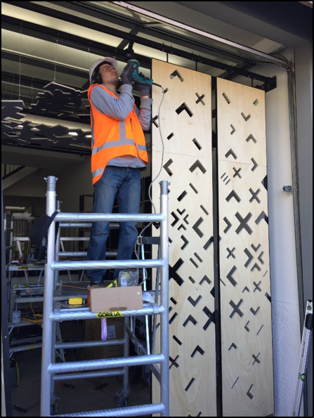
Discrepancies between the realities of the location and the design led to difficulties on-site. For example, the floor was not level, a fact that had not been recorded in the documentation, which led to set backs during installation. The privacy screens took longer to install and connections of the hollow metal sections proved challenging (Figure 7a). Although the systems used to install each individual cloud panel were well planned (Figure 7b); the composition and the installation of multiple panels on-site was not. We were required to reinstall grouped panels multiple times.
For most of the on-site installation, conventional building skills and methods were required. The only exception came when correcting the assemblage of the staircase hand rail balustrade and bookshelf. Despite the fact that the mock-ups had been tested, and their assemblage practiced in the workshop (Figure 6), the minor inconsistencies of the site were not measured accurately, and on-site installation was initially unsuccessful. It took a week longer than anticipated and the final installed design diverged slightly from the original workshop drawings.
This course and project enabled this group of students to acquire a varying set of skills, which were developed during the design and production of the Tech Futures Lab interior. A design-build project by nature, pushes those involved to their limits. Where many people struggle with the reality of deadlines and financial contracts, these challenges motivate the students taking part to do things they have not before.
Initially, we expected digital design technology to supplement our making skills. To an extent it did, but we now recognise that the more conventional skills of craft and technical knowledge are required in order to deliver a successful finished outcome. The hybrid use of digital and analogue techniques is therefore an essential part of the production workflow developed during this project. It was important for us to use technology as a tool and not simply as a system that drives and dictates the design and final product. It is more useful to discover potential problems in the design through making prototypes, rather than through the advice of our lecturers and technical staff. The process also developed a strong bond and workflow within the group.
Iterative prototyping as a process developed not just the fabrication and technologies used to realise the design, but also our individual skills. The virtual world did not represent the non-uniform world that we live in and we needed to compensate by re-designing, considering tolerance and adding detailed features into our digital models to ensure that the assembly process would go smoothly.
Burgess, T. and Mamou-Mani, A. (2015) ‘Entrepreneur makers: Digitally crafted, crowdfunded pavilions’, Architectural Design, 85(3), pp.130–135. https://doi.org/10.1002/ad.1912.
Chaszar, A. and Glymph, J. (2010) ‘CAD/CAM in the business of architecture, engineering and construction’ in Corser, R. (ed.) Fabricating architecture: Selected reading in digital design and manufacturing. New York: Princeton Architectural Press, pp.86–93.
Kieran, S, and Timberlake, J. (2004) Refabricating architecture: How manufacturing methodologies are poised to transform building construction. London: McGraw-Hill Education.
Lucas, R. (2016) Research methods for architecture. London: Laurence King Publishing.
Parsons, M. (2014) ‘Tolerance and customisation: A question of value’, Australian Design Review, 2 April. Available at: https://www.australiandesignreview.com/architecture/tolerance-and-customisation-a-question-of-value/ (Accessed 16 August 2018).
Thornton, J. (2005) ‘Fabrication research’ in Sheil, B. (ed.) Manufacturing the bespoke: Making and prototyping architecture. New Jersey: John Wiley and Sons, pp.58–78.
Willis, D. and Woodward, T. (2010) ‘Diminishing difficulty: Mass customisation and the digital production of architecture’ in Corser, R. (ed.) Fabricating architecture: selected reading in digital design and manufacturing. New York: Princeton Architectural Press, pp.184–208.
Rohini Contractor is a second year Master of Architecture Student at Unitec Institute of Technology. Her research interest centres on open source plywood construction. Contractor has been a student teaching assistant at Unitec for the past two years and has led a variety of collaborations with award-winning New Zealand architects. Over the past two years, her design-build research with plywood construction has been successfully exhibited at industry events in Auckland.
Adrian Janus is a second year Master of Architecture Student at Unitec Institute of Technology. Janus has been a student teaching assistant at Unitec for the past two years and has worked upon a variety of research design builds since the Tech Futures Lab Interior Project. His current research focus is investigating how computational architecture can create complex bamboo structures.
Yusef Patel is a part-time lecturer at Unitec Institute and a doctoral candidate at University of Auckland. His interests lie in the application of automated CNC fabrication technologies within the construction industry. He hosts a number of research experimental design-build projects every year for both undergraduate and postgraduate students to participate and learn from.